




Whats is a Synchronous Condenser?
A Synchronous Condenser (SC) is a rotating electrical machine that helps the power grid.
It contributes to system inertia, short-circuit capacity, and voltage and reactive power control. It is a cost-effective option compared to other options such as capacitor banks, reactor banks, STATCOM, SVC, and others.
The SC is part of the synchronous machine family. The difference is that the synchronous condenser does not generate energy like a synchronous generator, nor does it produce work like a synchronous motor. The SC consumes a small amount of energy from the grid (active power) to maintain operation.
Typically installed in a substation, it can be installed near power generation (wind farms, solar farms, etc.), in the transmission grid, in distribution, or even in industrial areas.
With power ranging from 10 MVA to over 300 MVA, these machines are typically built with salient poles, but can also have round rotor too.
Since they are synchronous machines, compensators require a direct current source to power the field winding (rotor winding), which is usually supplied by a static exciter (with brushes) or a brushless exciter. This is where an RTX POWER for each SC comes in!
With its appropriate construction, with salient poles, it allows operation with zero or even negative excitation current. An RTX POWER that operates in four quadrants is the solution!
Four-Quadrant Excitation System for Synchronous Condensers
The increasing entry into operation of large solar and wind power plants has demanded to increase the short-circuit level, improve voltage and reactive power control, and add inertia.
An efficient, economical, and technically viable alternative is the installation of Synchronous Condensers.
Synchronous condensers can have specific construction features, allowing excitation in the positive direction (traditional excitation) but also in the reverse direction (negative excitation). We are talking about an Excitation System operating in four quadrants.
Operating Principle
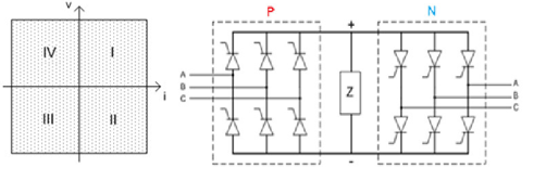
The figure shows the power structure for the four-quadrant excitation system, which consists of two three-phase Graetz rectifier bridges connected in antiparallel.
The polarity of the voltage applied to load Z is taken as a reference. The quadrants involved in the operation of this structure can be seen below:
Initially, the current flowing through load Z (generator field) comes from the positive bridge (P), which supplies the load with a positive voltage (quadrant I). At the end of the process, the current will flow in the opposite direction, being supplied by the negative bridge (N), with a negative voltage across the load (quadrant III).
In the 4-quadrant excitation system, the positive bridge corresponds to the forward field current and can operate during transient system conditions, or even in the case of self-excitation, with a negative field voltage (quadrant II). Similarly, the negative bridge can operate temporarily with positive field voltage (quadrant IV), while maintaining the reverse field current direction.
The difficulty encountered in the current reversion process using antiparallel bridges is accurately detecting the complete extinction of current in the positive bridge before releasing the control pulses to the negative bridge, and vice versa. Improper switching causes short circuits in the converters, subsequently opening the fuses.
Experience
REIVAX dominates the current reversal process in four-quadrant excitation systems. It has RTX POWER controllers in the largest machines in Latin America.