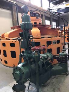
Combined Excitation/Governor system delivered for a 3.3MVA hydro unit in Canada, replacing a Woodward Gate Shaft mechanical governor and an AVR with obsolete components
The project scope included:
- One (1) cabinet for excitation/governor/unit functions
- One (1) EHI for the existing wicket gate distribution valve
- Two (2) MLDT position transducers
- Two (2) inductive speed pick-ups with new toothweel
By eliminating hardware associated with a separate governor controller and a separate excitation controller, a combined controller is able to achieve a higher Mean Time Between Failure (MTBF), hence increasing the overall reliability of the generating unit.
History – Woodward Gate shaft governor
While the purely mechanical governor for smaller hydro applications has been around since the late 1800’s, the most significant improvement occurred in 1911 when Elmer Woodward improved the mechanical governor by adding power amplification through hydraulic pressure allowing it to regulate larger hydraulic turbines. One of the first governors of this kind was the Gate shaft governor.
As with all mechanical systems, time and associated wear will eventually lead to a much-needed repair or replacement of the mechanical part. A digital governor controller eliminates any moving control parts associated with the fly-ball governor system, while still maintaining the existing hydraulic system.
Digital conversion of the fly-ball regulator
The fly-ball regulator on the existing governor was removed and a Reivax designed electro-hydraulic interface (EHI) with matching face plate was installed in its location. The new EHI assembly is responsible for controlling the flow to the distribution valve, which amplifies the oil flow to open or close the servo motor for the wicket gate (Francis) and runner blades (Kaplan/Bulb turbine).
The new EHI assembly included the following components:
Hydraulic manifold – A custom engineered adapter plate to direct the existing oil paths to the new control valves that are mounted on the manifold.
Proportional Control Valve (65PV) – Converts the 4-20mA electrical signal from the governor controller to a proportional oil flow, which drives the distribution valve. The proportional valve has onboard electronics providing a close-loop control.
Emergency solenoid valve (65R) – Operates with the activation of the 86M unit lock-out relay, independent of the governor controller. The valve will move in the fully closed position, causing the servomotor to close at the fastest rate allowable by the flow control adjustments as per IEEE std 125
Filtering system – The manifold is supplied with a duplex oil filter. Only one filter is in operation at a time and in the event the filter element is saturated, a clogging sensor will alarm and operation can be switched to the spare filter with the 3-way valve while maintenance is performed on the clogged filter.
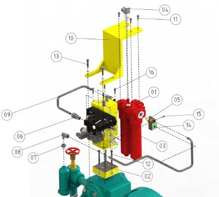
Position feedback sensor for the distributor valve – A Magnetostrictive Linear Displacement Transducer (MLDT) provides the position feedback of the servo motor for the closed-loop control in the governor controller. The MLDT sensor output (4-20mA) is proportional to the movement of the distributor valve.
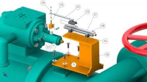
Position feedback sensor for the servo motor – A Magnetostrictive Linear Displacement Transducer (MLDT) provides the position feedback of the servo motor for the closed-loop control in the governor controller. The MLDT sensor output (4-20mA) is proportional to the movement of the servo motor.
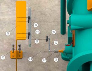
A new speed measuring system was also installed consisting of a new tooth wheel and two (2) inductive speed probes with mounting hardware.
The new governor control logic was integrated into a fully programmable high-speed controller, which also was responsible for the excitation control.
The following I/O was included:
- 48 Digital Inputs
- 32 Digital Outputs
- 16 Analog Inputs
- 16 Analog Outputs
- High-speed PT, CT and speed inputs
For maximum reliability, redundant controllers were offered, each one programmed with the excitation and governor controls. Hence, in the unlikely event a controller would stop working, an automatic transfer to the stand-by controller would take place with no change in operating output.
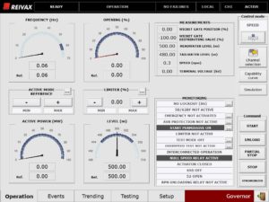
A 15” HMI panel was mounted on the control cabinet for local control, diagnostics and testing capabilities for both the excitation and governor system.
Ethernet communication with Modbus or DNP3.0 is available for interfacing with SCADA.

All tuning parameters can be changed directly on the HMI screen and is governed by levels of user name / password protection. A dedicated Sequence Of Events (SOE) screen with 1ms resolution and controller input for a IRIG-B time stamp helps the user to determine the exact timing and order of events and alarms.
Reivax system interfaces with the plant controller via Modbus over Ethernet.
The following main control functions are supplied with the system:
Governor
- Control Modes for Gate Opening, Frequency and Power with bumpless transfer
- Droop control
- Automatic Start / Stop with custom user starting configuration
- Automatic pre-load (reverse power prevention)
- Gate Limit control
- PT and back-up speed sensing
- On / Off line gain setting
- Grid connect & isolated grid mode
- Power vs Wicket Gate Opening look-up table
Excitation
- Control Modes for AUTO, MAN and VAr/PF (IEEE 421.5 ST4C / AC11) with bumpless transfer
- Power System Stabilizer (IEEE 421.5 PSS2B)
- Auto tuning feature
- Reactive compensation
- Automatic Start / Stop with custom user starting configuration
- Limiters (OEL, UEL, V/Hz, SCL, MEL)
- Protections (24, 27, 32, 37F, 40/32Q, 50/51, 59, 76F, 81O/U)
- Loss Of voltage sensing
- Voltage matching
Automation
- Start / Stop permissive and sequencing
- Supervision of generator temperatures, cooling water flows, oil levels
- Brake control
The software logic is fully configurable and functions can be added by the customer by using the supplied programming software.

