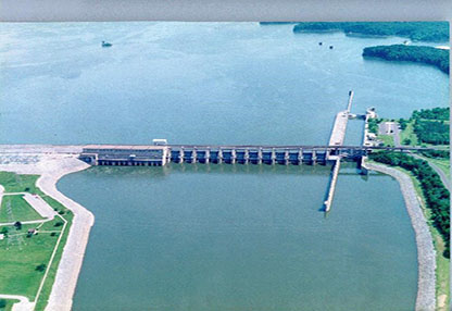
US Army Corps of Engineers Barkley Dam (KY) Static Excitation project , 4 x 36MVA, completed ahead of schedule by Reivax
Award Criteria and Scope Of Work
The evaluation factors were Experience, Past Performance, Design, Safety and Price. Reivax North America inc (Reivax) was awarded the contract in competition with other excitation OEMs, such as, ABB and Basler Electric.
Reivax was awarded the prime contract for this construction project and worked with various subcontractors for specific needs on the project, such as, removal/installation, asbestos and lead paint abatement, collector ring work and supply of AC and DC bus duct. The project scope included:
- Removal of the existing amplidyne MG set and exciter field poles
- Supply and installation of new excitation systems and transformers
- Supply and install of 15kV AC bus duct and 2kV DC bus duct systems
- Collector ring inspection, retrofit and brush and holder replacement
- Concrete work (demolition of concrete pedestal, floor and wall core drilling)
- All engineering, commissioning and model validation testing (MOD-026, PRC-024)
- Asbestos and lead paint abatement work
- Control board modifications and fiber optic SCADA interface to the exciter
All work was done according to the customer’s safety program EM 385-1-1 and Activity Hazard Analysis (AHAs) were developed for each feature of work.
Concrete work
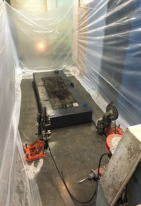
The work included the removal of the concrete slab used for the old amplidyne system as well as core drilling for floor and wall penetrations.
Concrete imaging was performed for all areas where cutting or drilling would be performed so that rebar, conduits etc. could be avoided.
Plastic sheeting was installed to contain any contaminants related to the concrete work and PPE was used by all personnel in the surrounding area.
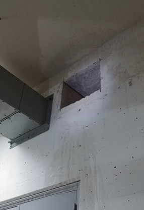
The layout of the new DC bus duct expanded over multiple floors.
Removal of exciter field poles and collector ring work
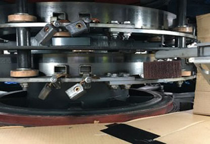
The exciter field poles were completely removed, as per the contract, to make room for the bus duct entering from the crawl space below the exciter housing.
The initial collector ring inspection confirmed that only polishing of the collector rings would be required. The polishing was made using a nylon web polishing stone with the unit spinning around 65 rpm. New brushes and holders were installed as well as a grounding brush and holder.
Bus duct work
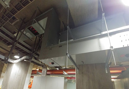
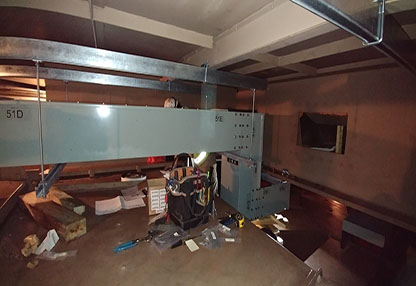
An existing inspection hatch for the 15kV generator bus was used to make the connection to the excitation transformer (PPT). The DC bus duct started below the excitation line-up and continued on the floor below, penetrating the generator housing, across the rotor spider and vertically all the way up to the collector ring itself. Due to the complexity of the bus run, various support structures were used to meet the seismic requirement. Seismic calculations were made for the bus duct to ensure the right quantity and type of support was being used. X-ray imaging was used for each anchoring location so that embedded obstacles could be avoided. Fire stoppers were added at each floor or wall penetration.
Control room work
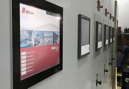
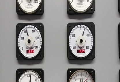
One (1) 15” remote HMI panel was installed into the unit control board with the ability to access each one of the four (4) excitation systems. Due to the distance between the locations of the excitation systems versus the control room, an optical fiber network was installed to connect to the unit SCADA system and the remote HMI panel as well. Other devices replaced in the control room included meters, switches and lights related to the excitation system as well as new field flashing breakers.
Excitation line-up
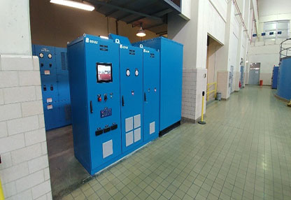
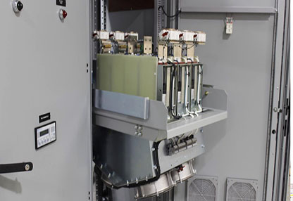
The new 1,600Adc static excitation line-up features an L-shaped design with the PPT, all painted in a blue colour to match the generators and other plant equipment. Redundant excitation controllers were used together with a single thyristor bridge, with redundant fans. An off-line draw-out bridge design provides for simple inspection, maintenance and bridge removal (picture from a different project).
Commissioning
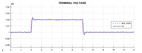
Various tests were performed during the commissioning, which also included model validation and protective relay coordination according to SERC. The below tests were performed:
- Off-line and on-line stability tests
- Limiter testing (OEL, UEL, V/Hz)
- Power System Stabilizer (PSS) testing
- Efficiency testing
- Stator Voltage wave form oscillograms
- Load Rejection testing
- Excitation system voltage response time
- Frequency response testing
- Full load testing

