WHAT IS AN EXCITATION SYSTEM?
INTRODUCTION
1. BASIC FUNCTION
EXCITATION SYSTEM CONCEPTS
1. CLOSED LOOP CONTROL
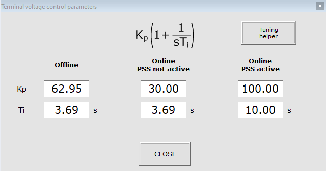
The tuning parameters associated with the control loop can easily be modified directly from the HMI. Three (3) sets of tuning parameters, allows for tailoring the optimal response for when a generator is not connected to the grid and for grid-connected mode depending if the Power System Stabilizer (PSS) is active or not :
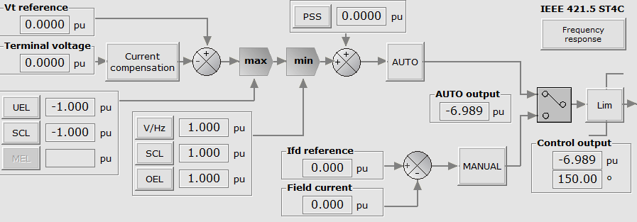
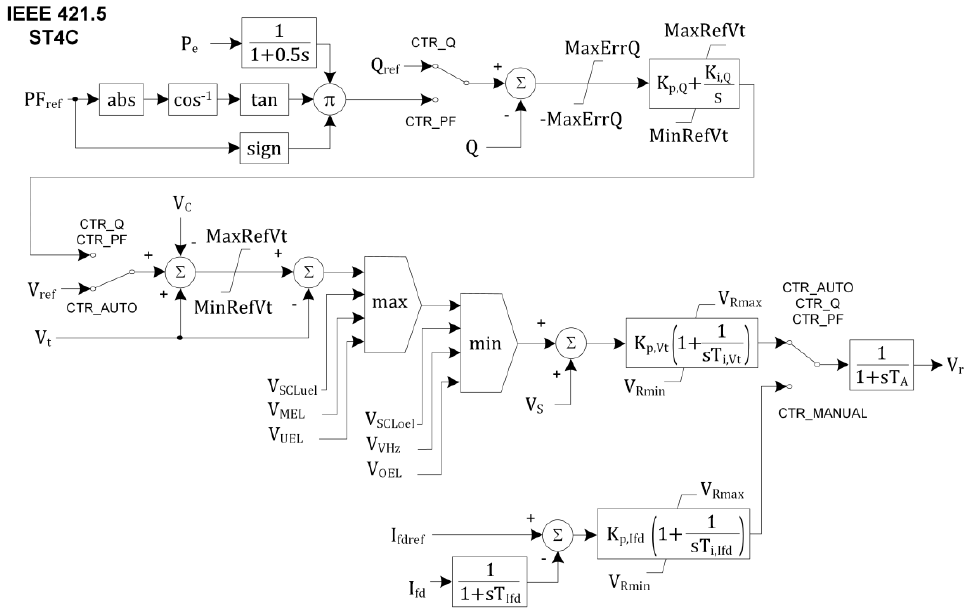
A sample diagram of the full control loop is shown below:
2. LIMITERS AND PROTECTIONS
Modern excitation systems are responsible for protecting the synchronous machine, the excitation system itself, and other devices. Limiters (OEL, UEL, VHz, SCL) and protections (24, 27, 32, 37F, 40/32Q, 50/51, 59, 59F, 76F, 81O/U) are software features designed to limit the machine operation in undesirable conditions, and are implemented as add-ons to the AVR control loop. Limiters will ensure that the machine is operated within the machines capability at all times, while the protection functions will protect the machine by initiating a trip. The excitation protective functions are typically duplicated in a separate unit protection relay. It is possible to disable the excitation protective functions and only rely on the unit protective relay or both protective functions can be utilized, in which case there needs to be a coordination between the two protective functions.
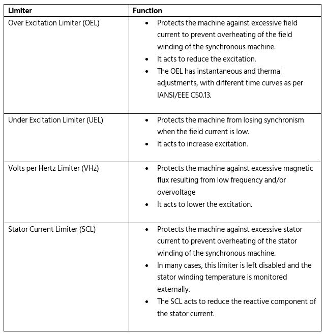
The most common limiters and their functions are given below:
2.1. OVER EXCITATION LIMITER (OEL)
For excitation systems manufactured by Reivax, limiters can easily be configured from the HMI. The simplified transfer function and configuration screen for the OEL is shown below corresponds to IEEE 421.5 OEL2C. The OEL is configured as an inverse-time characteristic curve as per IEEE/ANSI C50.13.
3. PROTECTION COORDINATION
Coordination between limiters, equipment limits and external protection relays is an important aspect of proper excitation system integration. Typically, coordination is performed as part of a protection study or model validation study, with the settings tested during commissioning of the equipment.
During commissioning, the OEL is drawn such that it overlaps the IEEE/ANSI C50.13 rotor thermal limit.
4. CAPABILITY CURVE
The capability curve of a synchronous machine is a graphical representation of the operating limits of the machine. The capability curve is a plot of the machine active power (MW) versus the reactive power (MVar). Typically, the following physical operating limits are represented:
- Rotor thermal limit
- Turbine limit
- Practical stability limit
- Pole slip limit
In addition, the following limiters are typically represented:
- Over Excitation Limiter (OEL)
- Under Excitation Limiter (UEL)
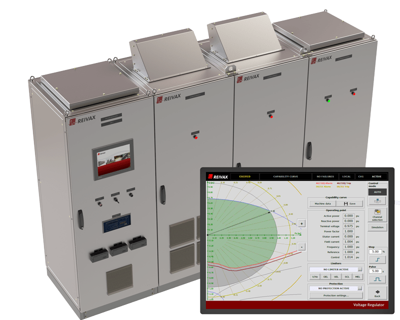
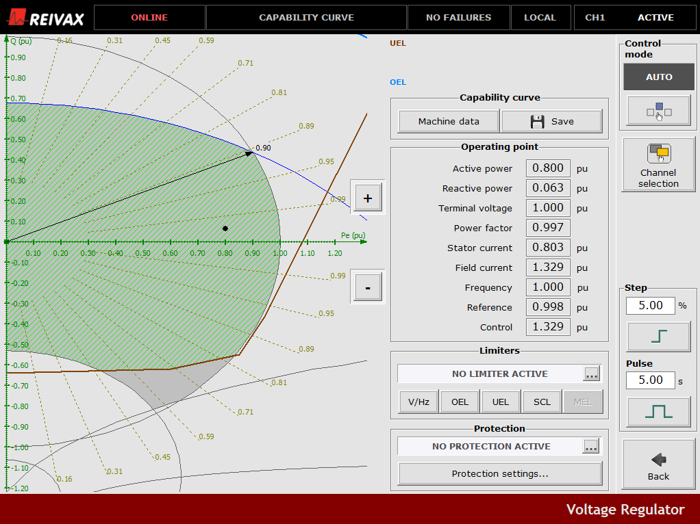
Excitation systems manufactured by Reivax include a dynamic capability curve that can be used to monitor operating conditions in real-time. An example of such a capability curve is shown below.
The capability curve shows the safe operating region of the machine, indicated in green, restricted by limiters and the physical limits of the machine. It also shows the operating point of the machine, in terms of active and reactive power (both quantities are shown in pu).
5. POWER SYTEM STABILIZER (PSS)
The Power System Stabilizer (PSS) is an add-on to the control loop of an excitation system that improves system stability by compensating for low frequency (0-5Hz) oscillations in the power system. This translates into a more stable generator output power, which can lead to significant savings due to reduced power losses. Power System Stabilizers offer superior cost effectiveness and have been found to produce millions of dollars in annual benefits for large utilities.
The PSS output is added to the AVR control loop. The image below shows the PSS summing junction as it appears on the transfer function of a Reivax excitation system.
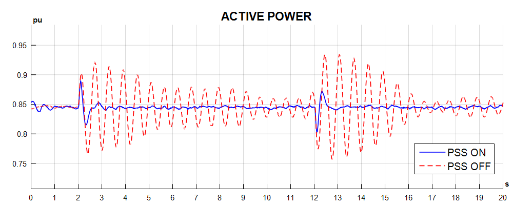
The graph below shows the response of a 32.5MW utility-scale generator with and without the PSS. A disturbance is introduced at the 2 and 12 second marks. The transient and steady-state stability are noticeably improved. Without the PSS, oscillations continue for about 10 seconds after the disturbance, whereas they are damped almost immediately when the PSS is turned on.
The Reivax PSS is compatible with the IEEE PSS2A and PSS2B models.
TYPES OF EXCITATION SYSTEMS
Different types of excitation systems have emerged over the years in the power industry. They are classified into two general categories, depending on the power source, rotating exciters and static exciters.
1. ROTATING EXCITATION SYSTEMS
In rotating excitation systems, there are two exciters: the main exciter and the pilot exciter. The main exciter supplies the pilot exciter, and the pilot exciter in turn directly supplies the synchronous machine. There are two sub-categories of rotating excitation systems: AC and DC.
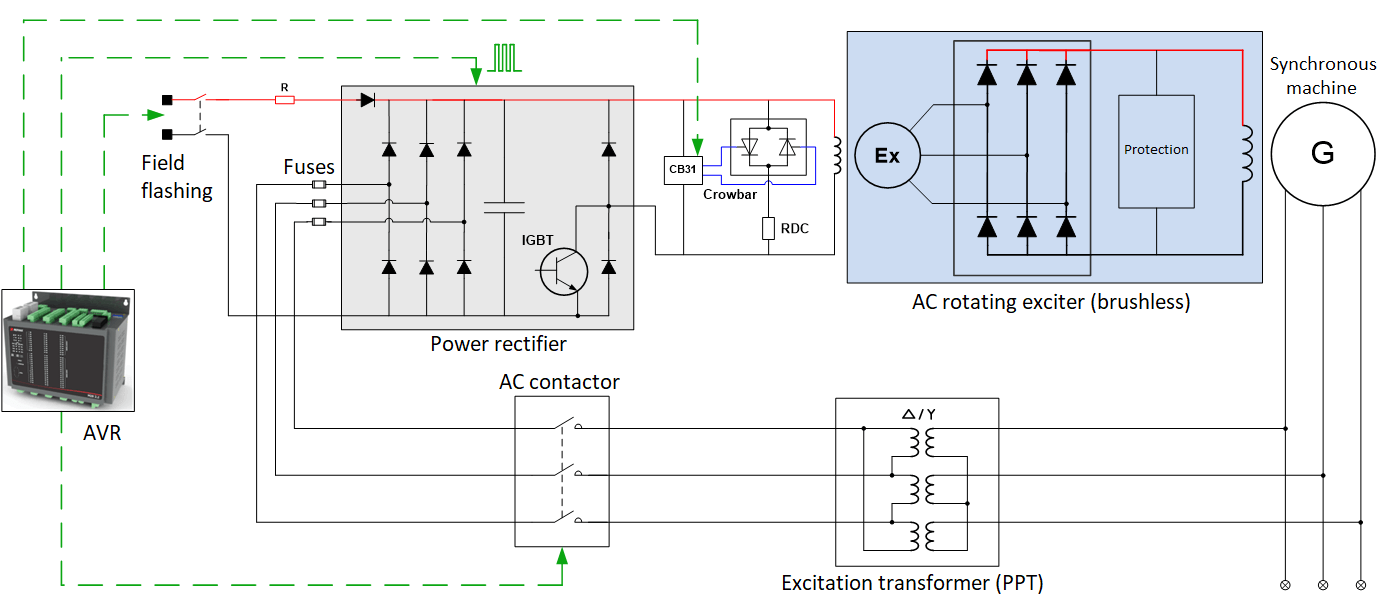
1.1. AC BRUSHLESS EXCITER
In an AC excitation system, the main power rectifier supplies an intermediary AC exciter. This AC exciter contains an internal power rectifier which then supplies the field winding of the synchronous machine.
A single-line diagram of an AC rotating exciter is shown below.
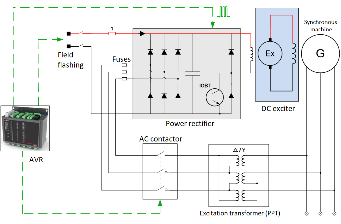
1.2. DC EXCITER
In a DC excitation system, the power rectifier supplies an intermediary DC exciter, which in turn supplies the field winding of the synchronous machine.
A single-line diagram of a DC rotating exciter is shown below.
2. STATIC EXCITATION SYSTEMS – TERMINAL-FED
In static excitation systems, the power rectifier directly supplies the field winding of the synchronous machine. There is no pilot exciter.
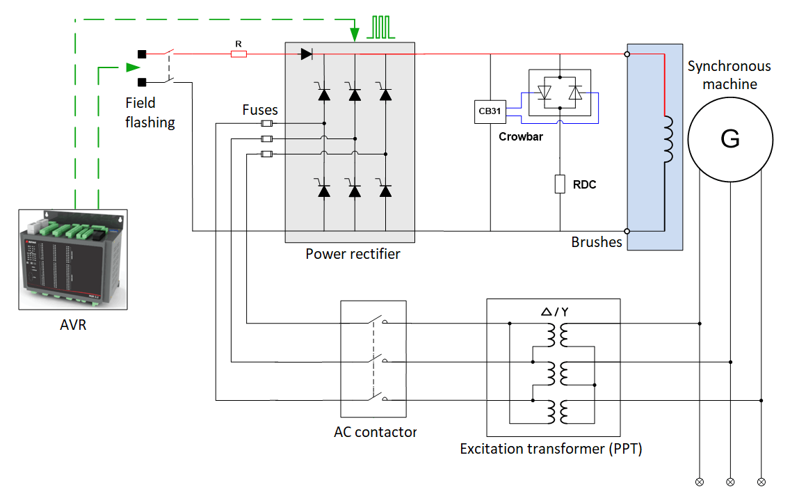
A static excitation system is terminal-fed (also called bus-fed) when the supply is taken from the machine itself through a power potential transformer (PPT). The primary of the PPT is connected to the stator of the machine and the secondary supplies power to the rectifier.
Static excitation systems are not inherently self-exciting, so they require an external supply to jump-start the excitation process and build up sufficient magnetic flux. This process is called field flashing.
2.1. ADVANTAGES OF STATIC EXCITATION SYSTEMS
Static excitation systems provide a number of benefits that make them an attractive option for synchronous machine control:
- Simple, reliable and cost-effective design
- Minimal maintenance requirements
- High performance and fast response characteristics
2.2. MAIN COMPONENTS
The main components of a static excitation system are listed below:
2.2.1. AUTOMATIC VOLTAGE REGULATOR (AVR)
The automatic voltage regulator (AVR), commonly known simply as voltage regulator, executes all control functions of the system, including the following:
- Operating breakers
- Sending firing pulses to bridges
- Responding to operator commands or grid disturbances
- Monitoring system I/Os and taking appropriate actions in response to them
- Maintaining the excitation system within safety and stability limits through the use of limiters and protections
- Issuing notifications to the plant SCADA system if anomalous conditions occur
- Tripping the excitation system if a critical failure or dangerous condition occurs
The main elements of an AVR are as follows:
- Control loop
- Limiters
- Power system stabilizer
Redundant control solutions are common. In a redundant configuration, there are two voltage regulators, one that executes the control functions while the other is in hot standby.
2.2.2. POWER RECTIFIER
Static excitation systems typically use a power rectifier that converts AC to DC current and provides a controlled field current to the synchronous machine. Power rectifiers typically use thyristor or IGBT technology.
Heat generation is a concern for the power rectifier. For bridge cooling, redundant fan sets are typically provided.
Redundant bridge configurations are common. In case multiple bridges are present, the excitation system will perform current equalization to balance the bridge outputs.
2.2.3. CONVERTER INTERFACE
The converter interface consists of all intermediary devices between the controller and power rectifier. It converts the control signal to firing pulses and isolates the control electronics from the power section.
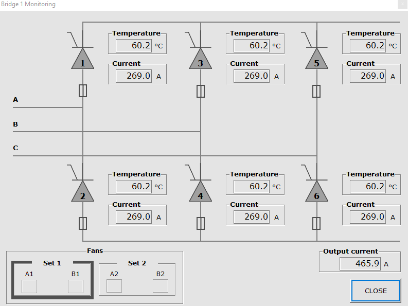
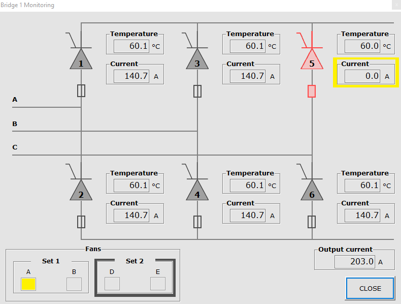
On excitation systems manufactured by Reivax, diagnostics tools for monitoring the power rectifier are provided on the HMI. The status of fans, fuses, and semiconductor temperatures can be checked in real-time, as shown below.